Products Category
WDQ1 plastic shell
Product Description
summary
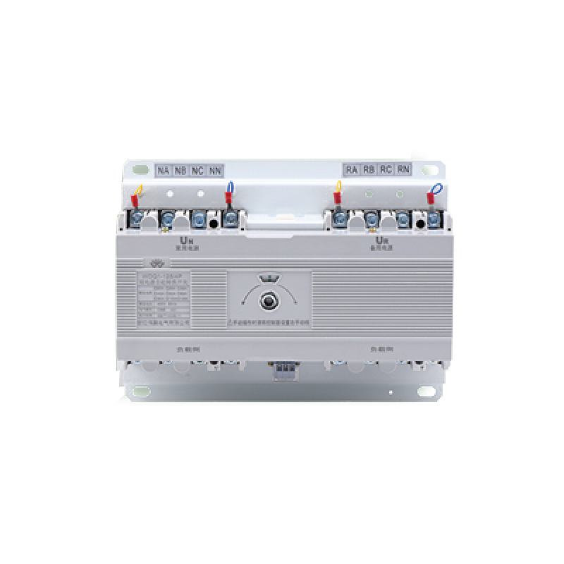
WDQ1 series dual power automatic transfer switch is applicable to the two-way power supply system with AC 50H and rated voltage of 690V and below. It can complete the automatic conversion of common power supply and standby power supply without manual operation.
This switch complies with the following clauses in the national standard of Automatic Transfer Switching Apparatus (KGB/T404811): the operating mechanism shall have reliable electrical and mechanical interlocking to prevent connecting the common power supply and the standby power supply at the same time.
The switch switches the load from the common power supply to the standby power supply within a predetermined time after the interruption of the detected phase A and all phase voltages of the common power supply, and returns the load to the common power supply when the common power supply returns to normal (with phase break protection function, phase A)
Installation and use method
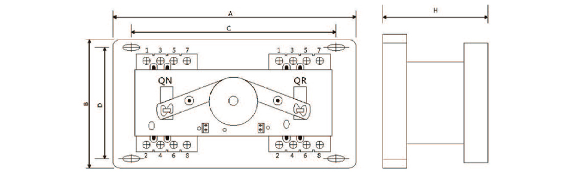
When wiring is installed, the common power supply N shall be connected to the common electrical actuating circuit breaker QN, and the standby power supply R shall be connected to the standby power actuating circuit breaker QR. When QN and QR are four wire circuit breakers, the wiring method shall follow the line diagram, where 1, 3 and 5 of QN and Q are three-phase (A, B, C) incoming terminals, 2, 4 and 6 are three-phase outgoing terminals, 7 are neutral line N incoming terminals, and 8 are neutral line outgoing terminals. If three pole special wire terminal KG is selected. See the coil connection for specific protection. The working power supply of the automatic controller of the dual power transfer switch is the phase A and the neutral line N at the incoming line ends of the circuit breaker QN and Q. During the installation and wiring of the automatic electric transfer switch, do not forget to connect, break or short circuit the sampling signal line of the local controller originally connected to the incoming line end of the circuit breaker, or it will not work normally.
The automatic working status is selected, and the switch is commonly used by default and has priority to be closed. During manual switching, the manual automatic button shall be placed in the manual operation position. When the handle is pushed to rotate counterclockwise to the terminal, the common power supply actuating circuit breaker QN is closed, and the standby power supply actuating circuit breaker QR is opened. When the handle is pushed to rotate clockwise to the terminal, the standby power supply actuating circuit breaker Q is closed: the common power supply actuating circuit breaker QN is opened.
Boundary and installation dimensions (mm)
|
Model |
A |
C |
B |
D |
H |
||||
|
3 Pole |
4 Pole |
3 Pole |
4 Pole |
3 Pole |
4 Pole |
3 Pole |
4 Pole |
||
|
WDQ1A-100 |
290 |
320 |
225 |
280 |
200 |
200 |
190 |
130 |
130 |
|
WDQ1A-225 |
330 |
365 |
290 |
335 |
215 |
215 |
195 |
195 |
155 |
|
WDQ1A-400 |
465 |
516 |
413 |
464 |
308 |
286 |
286 |
286 |
190 |
|
WDQ1A-630 |
525 |
596 |
474 |
545 |
318 |
320 |
295 |
295 |
195 |